Precision Direction Finding Antenna Array (RA-NS)

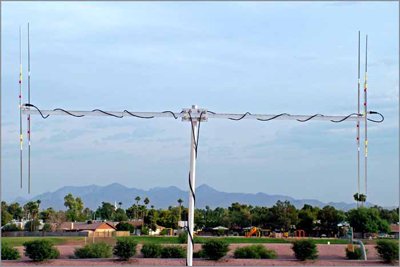
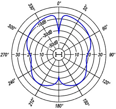
The RA-NS Precision Direction Finding Antenna array is designed for maximum accuracy and repeatability in direction finding with minimum field maintenance. The RA-NS uses two antennas, critically separated by a lightweight metal cross boom (model RA-CB). The received signals from both antennas are combined precisely out of phase, producing a pattern as shown in the plot below. The deep forward looking null (-10 to -30 dBV) in the center is bound on either side (+ or - 15 to 30 degrees), by a point of maximum gain (peaks). When this system is combined with a compass rose assembly and receiver capable of measuring signal strength (e.g. the TR-5), a repeatable accuracy of ± 0.5 to 2.0 degrees can be attained when working with animals in conditions of relative inactivity, and line of sight (LOS) conditions exist.

Key Features
- 1 degree bearing accuracy is possible using the deep forward null in the pattern.
- Accuracy is not dependent on the gain of the individual antennas selected.
- Selecting lower gain antennas and using horizontal polarization minimizes the received signal bounce.
- The use of the TAC-5 assures repeatable accuracy not possible with "old peak null" technology.
- The array has been mounted on vehicles for portability as well as permanent installations at fixed sites.
- The array comes standard with 2 17ft. cable lengths to accommodate mast heights up to 12 feet above ground level or vehicle level.
- Alternative cable lengths are available by special order for an additional charge.
| Model | Name / Description of Antenna in Array |
Antenna Gain |
|---|---|---|
| RA-NS-RA-2A Vertical polarization is standard (can be switched to horizontal polarization by using RA-NS-B bracket sold separately) |
RA-2A, 2 element "H" | 4 dBd |
| RA-NS-RA-3 | RA-3, 3-3 element Yagi | 6 dBd |
Each RA-NS array includes:
| Quantity | Description |
|---|---|
| 2 | Antennas (see choices in Model table above) |
| 1 | RA-CB cross boom |
| 1 | RA-TC "Tee" clamp (connects boom to mast) |
| 1 | TAC-5 Precision two port combiner |
| 2 | RW-3-17 cables (17 foot length accommodates mast heights up to 12 feet above ground level.) |
| 1 | RW-2 cable (connects Combiner to Receiver) |
| 2 | CON-BNC-CAP-F |
| 1 | Set of drawings for mast base, compass rose assembly, antenna mounting and cable dress |
* When ordering, specify the frequency band for the antennas:
- 148.0 - 152.0 MHz
- 150.0 - 154.0 MHz
- 158.0 - 162.0 MHz
- 164.0 - 168.0 MHz
- 168.0 - 172.0 MHz
- 216.0 - 220.0 MHz (available only with the RA-2A antennas)
Optional Equipment for RA-NS Arrays:
- RA-NS-B Bracket for switching a RA-NS-RA-2A from vertical to horizontal polarization
- RW-3-25-BNC 25 foot cable accommodates mast heights up to 20 feet above ground
User Must Provide:
| Quantity | Description |
|---|---|
| 1 | 1.25 - 1.7 inch O.D. Mast |
| 1 | Mast support, bearing (e.g. RA-TB) to allow rotation, and Compass Rose with ~1-degree increments |
Additional information important for users of the RA-NS system is included in the RA-NS Technical Note.
