RA-NS VHF Antenna Arrays
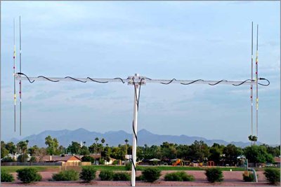
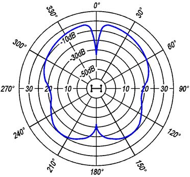
The RA-NS Precision Direction Finding Antenna array is designed for maximum accuracy and repeatability in direction finding with minimum field maintenance. The RA-NS uses two antennas, critically separated by a lightweight metal cross boom (model RA-CB). The received signals from both antennas are combined precisely out of phase, producing a pattern as shown in Figure 2. The deep forward looking null (-10 to -30 dBV) in the center is bound on either side (+ or - 15 to 30 degrees), by a point of maximum gain (peaks). When this system is combined with a compass rose assembly and receiver capable of measuring signal strength (e.g. the TR-5), a repeatable accuracy of ± 0.5 to 2.0 degrees can be attained when working with animals in conditions of relative inactivity, and line of sight (LOS) conditions exist.
The RA-NS should not be confused with the peak-null systems that were used for many years in the wildlife field. Under careful technical examination, those systems often fell far short of promised performance in obtaining consistent bearing accuracy of ± one degree over sustained periods of time and varying field conditions. There are sound technical reasons for the variable performance achieved with such systems. First, peak and null antenna patterns are obtained by attempting to control the phase of the radio signals received by each antenna through the use of coaxial cables of various lengths and impedance. Impedance transformation is accomplished in a like manner. The use of coaxial cables to accomplish phasing and the presence of an inline switching and control box create standing waves along the coaxial transmission lines. The waves result from improper impedance termination at, and within, the control unit. The standing waves along transmission lines effectively make the coaxial cables a portion of the antenna array itself, and result in a variable incongruity in the system which is most dramatically amplified under the changeable environmental conditions encountered in the field. Specifically, bearing accuracy degrades if the cables change in relative position to one another, the mounting mast, cross boom, or to ground objects. This problem is further amplified if cables, cable connections, or antenna terminations become wet. In general, the performance of such a system is best under mild, dry conditions and when animals are located at relatively short distances from the receiving antenna site (less than one mile typically). Consistent performance degrades rapidly as distance increases.
The RA-NS system does not rely on cabling to accomplish critical multi-purpose functions. Phasing and impedance transformation are controlled by the TAC-5 precision phase combiner, which presents 50 ohm impedance at any input or output port over the frequency range of interest regardless of the input impedance characteristics. The problems associated with the standing waves in coaxial transmission lines are alleviated by proper termination. The system is therefore insensitive to disturbances such as wet or randomly positioned cabling encountered under everyday field conditions. The system is very forgiving. Eyeball alignment of the antenna elements and confirmation of bearing to a beacon transmitter at a known location is adequate to maintain the accuracy of the system. Cabling does not have to be cut to critical lengths as long as the lengths of the two input cables are kept equal.
Key Features
- 1 degree bearing accuracy is possible using the deep forward null in the pattern.
- Accuracy is not dependent on the gain of the individual antennas selected.
- Selecting lower gain antennas and using horizontal polarization minimizes the received signal bounce.
- The use of the TAC-5 assures repeatable accuracy not possible with "old peak-null" technology.
- The array has been mounted on vehicles for portability as well as permanent installations at fixed sites.
Each RA-NS array includes:
| Quantity | Description |
|---|---|
| 2 | Antennas (either RA-2A or RA-3; in defined frequency bands) |
| 1 | RA-CB cross boom |
| 1 | RA-TC "Tee" clamp (connects boom to mast) |
| 1 | TAC-5 Precision two port combiner |
| 2 | RW-3-17 cables (17 foot length accommodates mast heights up to 12 feet above ground level.) |
| 1 | RW-2 cable (connects Combiner to Receiver) |
| 2 | CON-BNC-CAP-F |
| 1 | Set of drawings for mast base, compass rose assembly, antenna mounting and cable dress |
User Must Provide:
| Quantity | Description |
|---|---|
| 1 | 1.25 - 1.7 inch O.D. Mast |
| 1 | Mast support, bearing (e.g. RA-TB) to allow rotation, and Compass Rose with ~1-degree increments |
Mounting
The RA-NS RA-2A array can be utilized for both mobile and fixed site applications. Figure 3 shows the array with vertical polarization, which is standard. The array is small, lightweight, and presents little wind resistance. Further, only a 12 foot (4 m) mast is required for mounting the array. The array can be mounted in the bed of a pickup truck or on the roof of vehicles. If extensive or frequent movement of the array is required, it is best to develop a mount that can lie down in a truck bed to avoid vibration damage to the antenna.

Arrays using larger antennas, such as the RA-4A (5-element) or larger antennas should be mounted on a mast 20-30 feet above the ground or other conductive objects to avoid adverse proximity effects to the antennas. With use of the RA-3 and larger antennas with round main beams, the antennas can be mounted on the cross boom in either horizontal (Figures 4 and 7) or vertical polarization (Figures 5 and 6). Whether horizontally or vertically mounted, it is critical that both antennas are mounted in exactly the same way, not as mirror images.
Mounting the antennas in horizontal polarization typically reduces the impact of reflected signals (bounces) impacting the antenna array from the sides. Horizontal polarization is thus the preferred mounting technique for mountainous areas where signal bounce is a major problem.
A non-conductive cross-member (PVC or varnished wood) can be placed on the forward end of the antenna to assure that the physical relationship between beams remains constant. If this parallel relationship is disturbed, the main forward facing null will be shifted to one side or the other, and re-calibration of the system will be required.
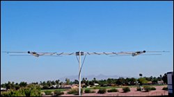 Figure 4. RA-NS-3 in Horizontal Polarization |
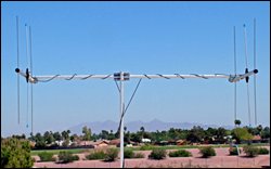 Figure 5. RA-NS-3 in Vertical Polarization |
Antenna Gain
The choice of antenna is determined by the system gain required and mounting considerations (systems using the smaller RA-2A, 2-element antennas are easier to mount). Unlike single antenna arrays where beam width is a function of the number of elements in the array, the accuracy of the RA-NS precision system is independent of antenna gain. Use of the RA-2A two-element antenna is preferred for many applications, including mounting in the bed of a pickup truck or the roof of a vehicle. In the RA-NS system, small antennas provide the same bearing accuracy as larger arrays; while having reduced weight, wind drag, and physical dimensions.
Antenna choice should be based on desired system sensitivity (operating range). Always use the smallest antenna possible to avoid confusion due to reflected signals.
All Telonics receiving antennas are trimmed to the specified frequency and tested for bandwidth and VSWR.
Antenna Patterns
The TAC-5 Null Combiner, shown in Figure 6, is a precision instrument. The TAC-5 forces a 180 degree phase shift between the paired antennas and thereby positions a narrow deep null directly in front of the array (Figures 9 and 10). The null is bound on either side by a point of maximum gain (peaks). The depth of the null or area of minimal signal reception, -10 to -30 dBV), is easily detected by the human ear. Precision direction finding (bearing determination) with repeatable ± 0.5-2.0 degree accuracy can be obtained with little training. The RA-NS series is far more effective for precision direction finding work than classic single Yagi beam arrays. As previously mentioned, bearing accuracy is not a function of antenna gain.
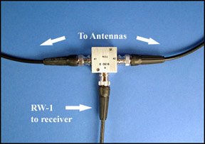
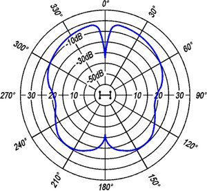 Figure 7. RA-2A Null Polarization Plot |
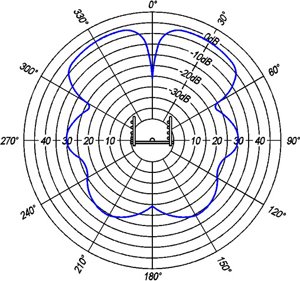 Figure 8. RA-4A Null Polarization Plot |
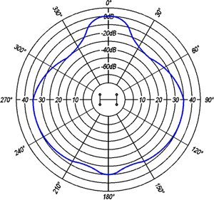
The RA-NS Antenna Array does not use a switch box to change between a null mode and a peak mode. If a peak mode is desired a TAC-4 or peak combiner can be used to replace the TAC-5. The antenna pattern in the peak mode is shown in Figure 9. Although the system was initially fielded with both TAC-4 and TAC-5 combiners, the 3 dB additional gain provided by the TAC-4 was almost undetectable to the human ear added only ~15-20% increase in range; thus, the TAC-4 is seldom used in field situations.
Although the TAC-5 is sealed, it is advisable to protect it from direct prolonged exposure to moisture. The unit should be mounted at the bottom of the mast, where it can be connected to the coaxial antenna feed lines when in use. If the study area receives a lot of precipitation, a drip loop should be made in the antenna cables just in front of the TAC-5. If antennas and cables are left out in the elements when not in use, the BNC cable connectors should be covered with CON-BNC-CAP-F connector caps to avoid mechanical damage and corrosion.
Cable Placement
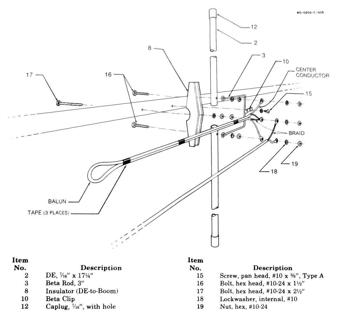
The coaxial cables used with the RA-2A antennas have a BNC-male termination on both ends; those used with the RA-3 3-element and larger “Yagi” antennas have a “pigtail” connection on the end that attaches to the antenna (the ground braid and center conductor of the cable are separated for attachment to the antenna). It is critical that the two coaxial cables connecting the antennas to the TAC-5 Combiner be exactly the same length (within 0.25 in.). Actual length is not critical as long as they are equal. Coaxial cable placement should be as close to the center beam of each antenna, the horizontal cross boom, and the vertical mast as possible. Particular attention should be paid to keep all cables away from the tips of the antenna elements, and cables should not be allowed to dangle between elements. The outer braid or shield of coaxial cables is at RF ground potential and will electrically detune the antenna if positioned between antenna elements. This results in improper (and sometimes erratic) feed impedance, changes in the phase relationship between elements, and a shift in the operating frequency of the array.
Antenna assembly instructions are provided with Telonics 3, 5, and 8-element antennas. The coaxial cable connection is to the driven element on these antennas as shown in Figure 10. The ground braid of the coaxial cable is connected to the middle bolt on the antenna, and the center conductor to the beta rod and the driven element as shown. If orienting the antennas with vertical polarization, Telonics convention is that the center conductor connection is on the upper side of the antenna; however, the critical aspect is that the two antennas are assembled and oriented the same, not as mirror images.
Note: Use Telonics type RW-3 cable for lengths less than 25 feet and type RW-5 cable for lengths from 25 to 100 feet.
Guying Considerations
If metal (conductive) guy wires are used to stabilize the mast, it is critical to attach such cables to the mast at a point two wavelengths (4 m, or ~12-feet at 150 MHz) below the tip of the lowest elements to avoid adversely biasing bearing measurements as a result of proximity effects to the antennas. If guy wires must be attached to the mast at a point closer than that to the antenna elements, nonconductive guys should be used.
Caution: Choose nonconductive guy material carefully. A material such as nylon is generally best, as it has the ability to wick water quickly and dry rapidly. Damp rope and twine is electrically conductive at VHF frequencies. Cotton and other soft fiber materials are undesirable as they remain damp for extended periods of time. Hollow rubber/fiber tubing cord with a steel wire in the center is unacceptable as well (i.e. clothesline cord).
Compass Rose
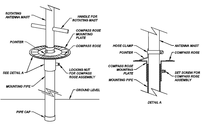
A compass rose assembly, as shown in Figure 11, is critical to obtaining fast, accurate bearing locations and for calibration of the system. The assembly shown can be modified to include the model RA-TB thrust bearing, thus allowing smooth rotation of the RA-NS Array during direction finding. (Note: In general, electrical antenna rotors are accurate to only ± 5 degrees in addition to other system errors. They are therefore unsuitable for precision work.)
Calibration for Bearing Location
Calibration of the RA-NS system requires use of a beacon or reference transmitter(s), such as such as Telonics TMB models. The array can be referenced to the beacon transmitter bearing at relative 0 degrees, or the entire array may be corrected to true north through the use of a compass.
Exacting electrical calibration of the RA-NS System is essential to obtaining high accuracy directional bearings. Mechanical and electrical bearing location may be slightly different. This could occur if the antenna elements of both antennas are not exactly parallel as a result of the initial attachment of the antennas to the cross boom, high winds, or abuse. Electrical calibration and periodic re-calibration at multiple points will provide assurance that the system is performing optimally and with repeatability.
Deployment and Positioning of Antenna Sites
No direction finding antenna array can compensate totally for signal bounce, multi-pathing, or the inability to receive signals in a certain location when the transmitter is out of range or a direct signal path is blocked by topography, dense vegetation, or other conditions. Antenna sites must be carefully chosen, especially if the site will be permanent and require a considerable investment of time and money to install. In general, bearings should be taken from three or more locations; and antenna locations should be selected as elevated areas that provide line-of-sight to as much of the study area as possible. Only an extremely unique study area could consistently allow position determination using only two antenna sites. Virtually every study area contains locations where the animal/transmitter is either out of range, hidden behind topography, located at a point where a bounce (reflected signal) gives false information to one or both sites, or located in an area directly between two antenna sites. Moving antenna sites closer together can help; however, error polygons may still be unacceptably large in parts of the study area. Areas at the edge of range performance from antenna sites may be especially problematic. Use of bearings from at least three sites helps provide confidence in a location assuming all three bearings nicely converge; or indication of a bounce signal or other difficulty if they do not. Use of bearings from three locations is illustrated in Figure 12.
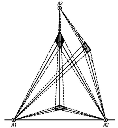
It is important to recognize that reflected (bounce) signals can result in the bearing to the strongest signal (or specifically the deep null) not being the actual direction to the transmitter. Each study area must be carefully evaluated and ground-truthed to determine the best antenna sites. Three sites are the minimum number required to do serious location determination via direction finding in most applications. Even then ambiguity can exist. Depending on the objectives of your study and the characteristics of the study area, five or more antenna sites may be applicable. In many study areas a minimum of five sites are absolutely required for conducting location work with the precision necessary for studies of habitat utilization. Following the establishment of fixed (or repeatedly used) receiving sites, the entire study area should be ground-truthed with a test transmitter. The transmitter is moved throughout the entire study area and its known locations are compared with the bearing locations obtained from each antenna site. Some sites will likely provide incorrect bearings because of topography or other factors. It is necessary to note antenna sites that cannot be relied upon when an animal is in a particular area. It is advisable to map these areas of inaccuracy for each site early in the study. Any directional fixes taken which fall within these areas can then be excluded in the data reduction phase.
Additional Information
More information on recommended aircraft search patterns: Telonics Quarterly V10, N1, Spring & Summer 1997, "Aircraft Tracking"
Additional links to the following Telonics Quarterly articles:
