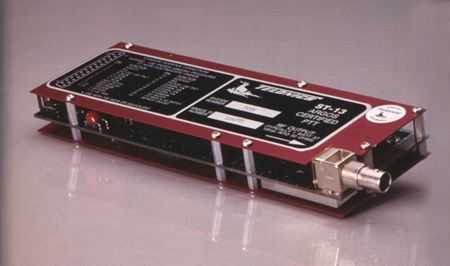
Telonics ST-13 Argos Certified PTT
The information below on discontinued products is provided for individuals who are still using these older systems. Product descriptions may be time sensitive or even outdated. Please contact Telonics if you have questions.
Features
The ST-13 is designed for environmental research applications with an emphasis on oceanography and meteorology programs. The backbone of a highly adaptive sensor and data collection system, the ST-13 is used in conjunction with Argos Data Processing and/or Local User Terminals (LUTs).
Specifically, the ST-13 can be configured to:
- Collect high accuracy temperature or pressure data,
- Establish drogue status for oceanographic applications,
- Interface to an established data collection system via an asynchronous serial interface, and
- Control a GPS receiver and report GPS positions.
The core ST-13 unit is available with a variety of hardware and software options that allow it to be custom configured for specific tasks. All specified options were developed to meet specific research needs. Both hardware and software can be altered for a wide array of additional purposes, generally at minimal cost. The flexibility of the ST-13 will support the development of additional sensors and new software data collection regimes.
Additional information on the ST-13 is available in the Telonics Quarterly.
(PDF format, TQ Vol. 6, Number 3, "The New ST-13 Argos PTT.")
Options
High Accuracy Temperature Option 271
Two high accuracy temperature ranges have been developed specifically for users in the oceanographic field. The hardware configurations, with appropriate software, allow researchers to utilize the ST-13 in a temperature monitoring role. Up to 8 thermistors can be monitored, processed and the data uplinked to the NOAA polar orbiting satellites to provide information about sea surface and subsurface temperatures.
| Option |
Thermistor1 |
Number of Thermistor Ports |
Temperature Range |
Accuracy3 |
| 271 |
Linear2
YSI 44018 |
1 - 8 |
+10 to +38° C
OR
-2 to +38° C |
± 0.05° C
OR
± 0.05° C |
- Recommended thermistors are produced by Yellowsprings Instrument Co., Inc. and must be purchased separately.
- Linear thermistors are designed to maintain the same resolution over the full temperature range and, following calibration, are described by a simple linear equation in the form y = mx+b, where m is the slope and b is the y-intercept. Standard values for +10 to +38° C: m = 0.0274 C/count, b = +10.0° C. Standard values for -2 to +38° C: m = 0.0391 C/count, b = -200° C.
- Standard accuracy assumes the ST-13 10-bit resolution and high accuracy calibration techniques.
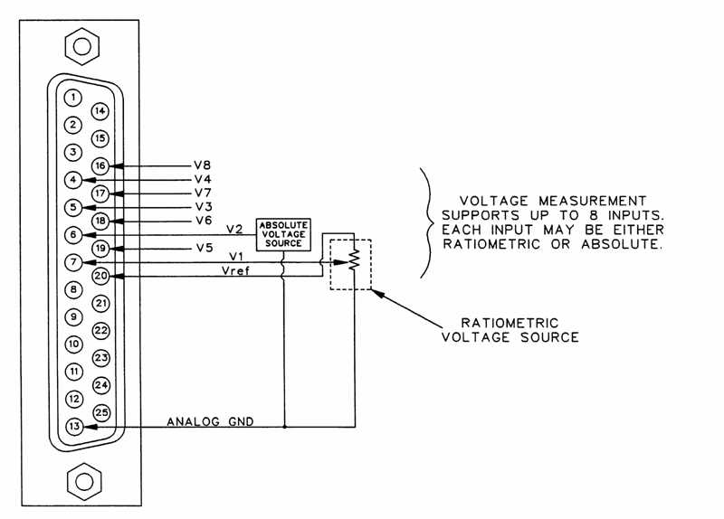
Temperature Measurement Accuracy
The capabilities of the ST-13 include a highly accurate temperature measurement system. Temperatures are sampled via thermilinear thermistor networks. These networks produce output voltages which are measured in such a manner as to eliminate scaling, offset and signal conditioning errors. Figures 1 and 2 show theoretical and actual accuracies of temperature measurements obtainable with the ST-13 in conjunction with a YSI #44204 thermilinear network over the temperature range of -2 to +38° C.
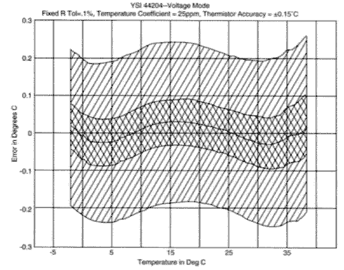
Figure 1: The center line of the graph is the nominal nonlinearity of the thermister network. Surrounding the nominal nonlinerarity line are error bands. The inner band shows how much error may be caused by the tolerance and temperature coefficient of the fixed resistors. The outer error band shows how much error can be caused by the interchangeability of the thermistor itself. The fixed resistors that are installed in the ST-13 have a 0.1% tolerance and a 25 ppm per degree C temperature coefficient. The interchangeability of the YSI #44018 thermistor (part of the #44204 Thermilinear Network) is 0.15° C.
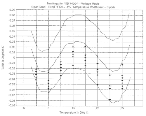
Figure 2: Figure 2 shows actual performance of a sample of eight ST-13 units. Instead of using an actual thermistor and temperature bath, two resistance decade boxes were used to simulate the thermistor over the temperature range. The decade boxes were 'calibrated' using a high quality digital ohm meter to within one ohm of the resistance values stated in the YSI #44018 data sheet. The discrete data points show the measurements obtained from the sample. The nominal nonlinearity is also shown along with the error band due to the tolerance of the 0.1% fixed resistors. Since the ST-13 units remained at room temperature throughout this test, the temperature coefficient of the fixed resistors is not considered in the calculations of this error band. Note that fewer that eight data points appear at each temperature since several data points fall directly on top of one another.
Low Cost Temperature Option 200
Designed for users who require monitoring of a single temperature channel, but with less absolute accuracy than provided by the high accuracy temperature options. While the option is less expensive, it is capable of high resolution temperature measurements within ± 2.0° C absolute accuracy. The single temperature sensing element is contained within the ST-13 packaging and is not suited for remote deployment outboard of the ST-13. Designed for the -40 to +70 C° range.
Drogue Monitoring Options
Oceanographic studies often require monitoring the presence or absence of a subsurface drogue attached to a drifting buoy. The following options can be used in a variety of drogue monitoring applications.
- Salt Water Switch Option 300
The ST-13 can be configured with saltwater switch circuitry and used as a submergence detector. (Note: In some buoy designs, the periodic submergence of the buoy signifies the presence of the drogue.) This configuration requires an active probe and ground placed on the external surface of the buoy. When the buoy is submerged (an indication that the drogue is present in some buoy configurations), the saltwater switch is closed by the seawater path. Upon resurfacing, the saltwater connection between the two probes is broken. The addition of the saltwater switch circuitry increases the quiescent current drain of the core unit by approximately 100 ma. The non-fouling circuitry employed does not present a DC current bias which might result in electrode build-up and the resultant latent failures often associated with simple 'saltwater switches' provided by other suppliers in the past.
- Salt Water Switch Option 301
Offers the capabilities described above, but the saltwater switch circuitry also initiates PTT transmission upon surfacing if the minimum Argos repetition interval has been canceled. Transmissions are suspended underwater, thus avoiding wasting current drain required for transmission when the buoy is below the surface.
- Position Sensor Option 052
Allows relative position changes to be monitored by means of a remote gravity switch (installed by the user external to the ST-13), and incorporates this information as part of the transmission. This approach has been implemented in studies where loss of the drogue results in the change of the relative position of the buoy.
- Position Sensor Option 053
Monitors transitions of remote gravity switch (installed by user external to the ST-13) so that the change in position is recorded rather than the actual position of the switch.
Atmospheric Pressure Transducer Option 800
Designed to monitor altitude and barometric pressure, the option allows the ST-13 to be interfaced with an Atmospheric Pressure Transducer (Intellisensor II, AIR Model #2B-2A). The transducer currently being utilized has an operational temperature range of +5 to +40° C. The full scale barometric pressure accuracy is ±5 mb with a resolution of 0.01 mb.
Asynchronous Serial Connection Option 101
Provides the ability to conduct communications from a host data collection system (provided by the user) to the ST-13 across an asynchronous serial interface. The user's system is able to 'wake up' the ST-13, issue commands and send data that is then uplinked to an Argos receiver onboard a Polar Orbiting Satellite. The asynchronous communication protocol between the host and the ST-13 can be configured to support transmit (TXD) and receive (RXD) lines, and a wakeup line. In this configuration, a hand-shake protocol acknowledges commands sent by the host to the ST-13. Alternatively, the removal of the RXD line makes the ST-13 interface a unidirectional control interface. An auto-repeat function allows retransmission of the same data stream without additional commands from the user. A FailSale mode is available which turns the ST-13 on if the communications interface is disrupted or damaged. The ST-13 converts the data to the approved Argos Format for transmission prior to uplinking the message to a satellite. This configuration allows the user the flexibility of controlling the ST-13 but does not require recertification through Argos.
Serial Communication Protocol
The ST-13 supports the following serial communication capabilities:
- Asynchronous serial utilizing standard NRZ format.
- One start bit, eight data bits, one stop bit, no parity.
- Supports baud rates of 300, 600, 1200 and 2400.
- Data are transmitted least significant bit first.
Command Data
Command bytes and data bytes sent from the host to the ST-13 are always 8-bit binary values. They are not ASCII characters. The user must ensure that the host's UART is configured to send complete 8-bit values without parity.
Command Initiation
The host computer initiates each command by activating the wake-up line to the ST-13. The wake-up link requires a momentary active low signal 100 milliseconds in duration, after which it must be reset high. The host must wait
20 milliseconds after the wake-up signal has been returned to the high state before it initiates the serial transmission of the command byte. After the delay, the host transmits the command byte followed by any additional data bytes appropriate for that particular command.
After the ST-13 receives the command and data from the host, the ST-13 will respond with an ACK if the command is valid, or an NAK if the command is not valid. After sending its response, the ST-13 will then go back to sleep and must be reawakened before another command can be transmitted from the host.
Commands
Commands take the form of single byte (8 bit) values that define operations to be performed by the ST-13. The following command summary (see table 2) is a general description of the protocol. A complete User's Manual for the asynchronous serial protocol is available on request.
| Command (Binary) |
Function |
| (1) 00010xxx |
Store Data 1: Store the data (8 bit binary values) following the command byte in ST-13 Buffer Number 1, but do not transmit. The "xxx" value is used to specify an index into the ST-13's internal table of 8 Argos ID Codes. The value of "xxx" varies from zero to seven and specifies which ID Code will be used to identify the user's data when it is transmitted following the command byte. The Argos ID Codes that are programmed into the ST-13 at the factory include Argos message data length specifications. The data length can be expressed as 4, 8, 12, 16, 20, 24, 28 or 32 bytes. |
| (2) 00100xxx |
Store Data 2: Store the data bytes following the command byte in ST-13 Buffer Number 2. |
| (3) 00110xxx |
Store and Transmit 1: Store the following data in Buffer Number 1 and transmit it immediately. |
| (4) 01000xxx |
Store and Transmit 2: Same as above, except that data will be stored in Buffer Number 2 and then immediately
transmitted. |
| (5) 01010xxx |
Transmit 1: Transmit the data previously stored in Buffer Number 1. No data follows this command byte. The three bit value "xxx" specifies one of a possible eight (0-7) different Argos ID Codes. |
| (6) 01100xxx |
Transmit 2: Transmit the data previously stored in Buffer Number 2. |
| (7) 01110zyx |
Auto-Repeat: Automatic repeat RF transmission command. This command consists of one or three bytes, depending on whether default values are used for repetition rate and repetition count. If the default value option is selected (bit "y" set to 1), then the entire command consists of one byte. Otherwise, the host supplies the repetition rate and count (bit "y" set to 0) and the command consists of three bytes. |
| (8) 100000000 |
Cancel Auto-Repeat: Cancel automatic repeat RF transmission function initiated via command 7 (Auto-Repeat). |
| (9) 10110000 |
Null Command: The command does not initiate a transmission. It may be sent periodically to let the ST-13 know that the host is still properly functioning so that the ST-13 will not enter a FailSafe mode of operation. The ST-13 will respond by sending an ACK to the host so the host may know that the serial interface is OK. |
| (10) 11000000 |
Disable TEC: Disable Transmit Error Counts mode. |
| (11) 11010000 |
Enable TEC: Transmit Error Count mode. This command causes the "Error Count Marker," the "Error Count," and the four most recent error codes (total of four bytes) to be transmitted in the first four bytes of the data portion of the Argos message. |
| (12) 11100000 |
Disable FailSafe mode: This command must be followed by 16 bytes of hexadecimal qualification data as follows: AA,AA,AA,AA,AA,AA ..... AA,AA,AA. The value "AA" is 10101010 in binary. This command resets the internal counter which controls FailSafe duty cycle. |
| (13) 11110000 |
This single byte command is used to enable the FailSafe mode of operation. This command starts (but does not reset) the internal time counters controlling FailSafe duty cycle. |
External Chain Interface Option 900
Provides an interface between the ST-13 and up to 32 "intelligent" sensor modules (sold separately). A full asynchronous communication protocol is established and maintained between the modules and the ST-13. The modules are capable of collecting information such as subsurface and surface temperatures, and subsurface pressures. That data are then processed into a reduced form capable of being sent across the communication line to the ST-13. The ST-13 incorporates the formatted data and uplinks the information to the satellite. Please consult the laboratory for information on specific modules.
Application Programs
Different program applications can be placed into the ST-13 ROM to support various user applications. For example, a user may require sea surface temperatures and drogue status of the buoy. If an application program has already been written to acquire temperature and drogue status, then the task is usually simple.
Most ST-13 application software programs include numerous user selectable parameters that can be tailored to meet individual requirements. For example, the user can select the sampling regime in temperature monitoring applications. The time between samples, the number of samples required, and the ability to average samples can also be selected. In addition, most software application programs for the ST-13 utilize seasonal duty cycle timing. This capability allows researchers to select periods of time when the Argos transmitter is turned ON and OFF. This function can extend the life of PTTs substantially over continuous operation modes. The researcher selects time periods to operate the PTT, thus insuring the unit is ON during periods of maximum satellite visibility and OFF when the frequency of overpasses is reduced. A separate product, the Telonics Overpass Prediction and Display Software (TSP/TSD) is available to enable users to accurately define "windows" of high frequency of satellite overpasses for any specific areas worldwide. The programs can be installed on most IBM personal computers.
The basic design of the TSP/TSD ST-13 PTT is based on a microprocessor controller. Various new software application programs can be written to change the role and mission of the PTT. Our in-house design staff works with researchers on specific projects to develop software that meets their exact goals and requirements at minimal cost to the user. A software library has been established for the ST-13, and specific software application programs can be factory installed into the unit at no additional charge to the researcher.
If the user requires an interface to a new sensor or a new data collection and analysis scenario, then a new software application program may be required. Under these circumstances, non-recurring engineering may be required to meet the user's needs.
Accessories
The following accessories are available with the ST-13.
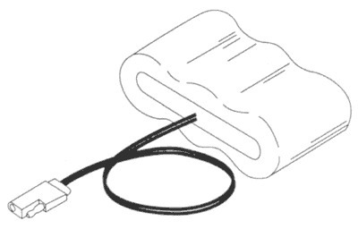
Battery Packs
The ST-13 can utilize either lithium or alkaline battery packs. Telonics produces custom battery packs for special applications, and the packs are diode protected for parallel operation. In the case of lithium battery packs, current and thermal fuses are provided in compliance with safety requirements. Power leads include a keyed connector to avoid accidental application of reversed polarity. The performance and capacity of any battery pack is dependent upon duty cycle and operating temperature as well as other factors. Careful selection of the appropriate power pack is critical to performance in the field. Please consult our engineering staff if you have questions concerning our power supply options. All shipments of battery packs by Telonics are in strict compliance with D.O.T. regulations.
Antennas
Antennas are often the most misunderstood and misapplied aspect of communication systems. The antenna configuration at the satellite is controlled by Argos and NOAA. The user should be involved in the selection of the antenna to be used on the Argos PTT. The selection of the proper antenna configuration is based upon many factors including the physical configuration of the buoy or balloon, the proximity of the antenna to metal, the presence or absence of ground plane, and the physical abuse that the antenna may experience. Telonics produces several specialized antenna configurations for various ST-13 applications.
They include:
- CM002421 half-wave ground plane independent antenna
- CM000849-401 quarter-wave antenna
- CM001331-001 "spider" antenna that essentially provides a ground plane and quarter-wave radiating element
- CM001968 special half-wave ground plane independent marine antenna
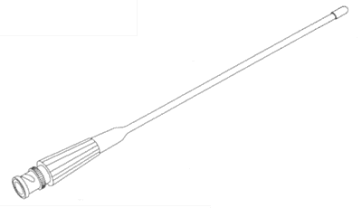
CM002421 Half-wave Antenna
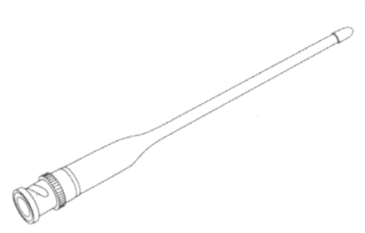
CM000849-401 Quarter-wave Antenna
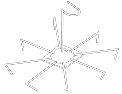
CM001331-001 Spider Antenna
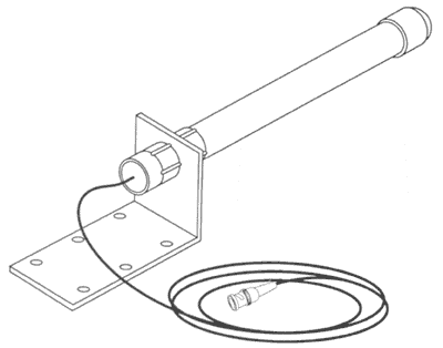
CM001968 Special Half-wave Marine Antenna
All of these antennas have been used successfully in Argos applications. Our engineers will be happy to consult with you on the selection of a proper antenna for application to your particular study design.
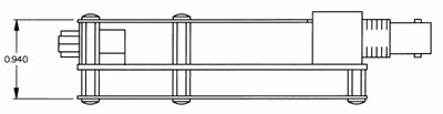
ST-13 RF Module
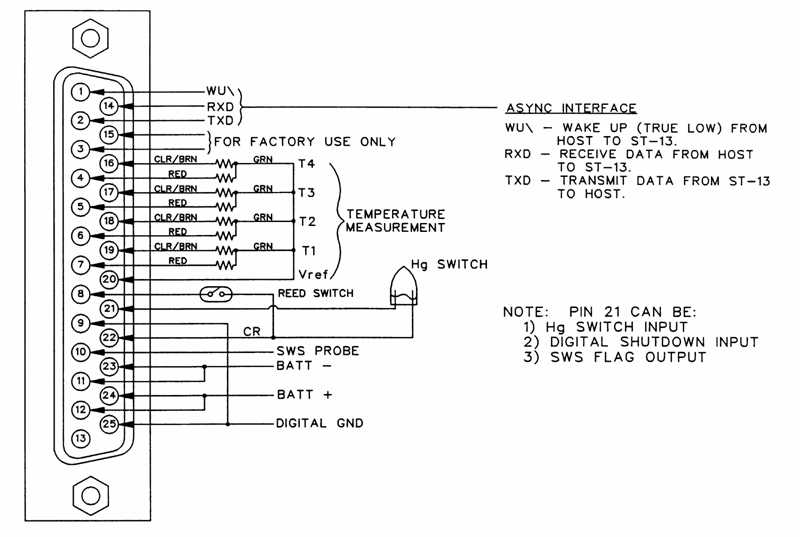
The ST-13 RF Module is available as a separate component for those researchers who wish to interface an RF Module with their own digital control circuitry. It is important to understand that when the RF Module is sold for use with an uncertified controller, it is necessary for the user to certify the complete assembly with Argos prior to any deployment. This is the user's responsibility even though the ST-13 RF Module has been certified previously in conjunction with Telonics digital control circuitry. The RF Module utilizes a DB-25 connector with a 7-pin interface for control logic. Additionally, connectors are provided for the antenna ground and +V supply voltage (+7.0 to +14.0 VDC). Interface and control specifications are available upon request in the Argos ST-13 RF Module manual.
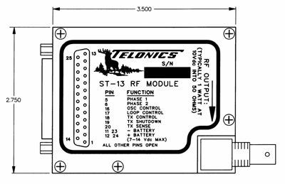
RF Module Top View
RF Module Side View
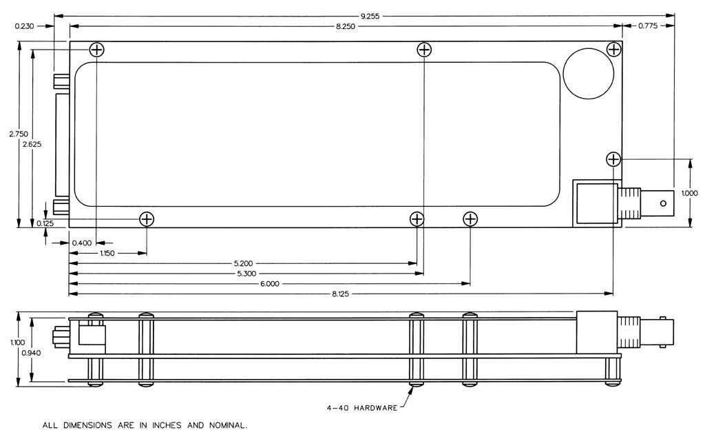
Specifications
| Argos Certified PTT | Model CM 10 001-004 |
|---|
| Weight | <200 g |
|---|
| Size | See Figure 12 |
|---|
| Frequency | 401.650 MHz (per Argos specifications) |
|---|
| Operating Temperature Range | Option 003, 0 to 50° C; Option 004, -40 to +70° C; Option 005, -40 to +60° C |
|---|
| Storage Temperature Range | -60 to +80° C |
|---|
| Humidity | 90% Non-condensing |
|---|
| Power Output and Peak Current | 1.35 W/525 µA at 14.0 VDC during transmission (50 Ω load); 500 mW/350 mA at 7.0 VDC during transmission (50 Ω LOAD). |
|---|
| Voltage | +7.0 VDC to 14.0 VDC |
|---|
| Quiescent Current | <100 ma MAXIMUM (65ma typical) |
|---|
| Case Polarity | Negative (-) Ground |
|---|
| RF Output | BNC female connector on unit |
|---|
| RF Output Impedance | 50 Ω |
|---|
| Interface Connector | DB-25 female (for digital and analog signals) Inputs are static sensitive. |
|---|
| On-Off Switching | Option 061 - A normally open (N.O.) switch turns the PTT on. |
|---|
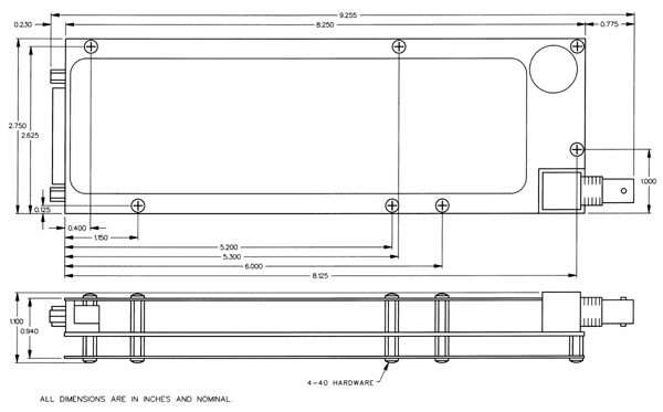
Figure 12 (click the image to enlarge)
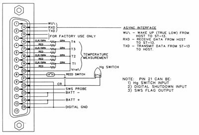
Figure 13 DB-25 Interface Pin Assignments (click the image to enlarge)
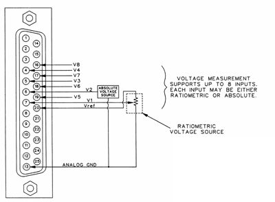
Figure 14 DB-25 Interface Alternate Pin Assignments (click the image to enlarge)
Service Commitment
Since 1970, Telonics has built a reputation based on product quality, product support, service, and customer satisfaction. Telonics strives to produce the highest quality products, and to support those products accordingly.
Because of extreme conditions and the unpredictable nature associated with most telemetry applications, problems occasionally arise. Most problems can be resolved quickly. In all cases, we hope to be able to work in partnership with users to resolve problems to the user's satisfaction and to uphold our demonstrated commitment to excellence. If problems should arise, all products must be returned to our factory for failure analysis.
Warranty - Show
Telonics warrants its products to be free from defects in material and workmanship for a period of one year from the date acquired. Telonics does not warrant batteries.
If a defect occurs, return the equipment to us within the proper time frame at the following address: TELONICS, 932 E. IMPALA AVENUE, MESA AZ USA 85204-6699. Damage to any equipment resulting from misuse, accidents, unauthorized service, extreme conditions, or other causes, is excluded from this warranty. Telonics does not assume responsibility for loss or damage to equipment during shipment. Telonics does not assume responsibility for delays resulting from shipment on commercial or private carriers. We insure all equipment shipped from our facility and suggest that shipments to Telonics also be insured.
Upon the timely return to our facility, if defective, the product will be replaced or repaired at our discretion at no cost to the customer. This remedy is the exclusive remedy. This product is supplied without any further warranties or conditions, expressed or implied, including warranties of merchantability, quality or fitness for particular reason or those arising by laws, statutes or trade usage or course of dealing.
The entire risk, as to the results and performance of the product, is assumed by the customer. Neither Telonics, nor its suppliers, shall have any liability to the customer or any other person or entity for any indirect, incidental, special, or consequential damage whatsoever, regardless whether Telonics has been told of the possibility of such damages or that such damages might be foreseeable. Telonics has no responsibility or liability for the claims of any third party. The maximum aggregate to the customer, of Telonics and its suppliers, shall not exceed the amount paid by the customer for the product.