Aircraft Receiving Systems
Aircraft have been used for many years to aid in tracking of VHF transmitters. Specific equipment used can vary depending on the type of aircraft, how those in the aircraft communicate, and how often such tracking is done, but a typical system would include the following components:
- Telemetry Receiver: e.g. Telonics TR-8, or the discontinued TR-5, TR-4 or TR-2/TS-1
- Two, RA-AHS, 2-element, directional antennas
- TAB-# bracket (pair), for attachment of RA-2AHS to the struts of a high-winged plane
- Two, RW-3-17 (BNC/BNC), or similar length coaxial cables to connect RA-2AHS antennas to the TAC-2 antenna control unit
- TAC-2 Control Unit, allows switching between the two RA-2AHS antennas
- RW-2 coaxial cable, to connect the TAC-2 to the receiver
- Audio distribution system, with headphones or headset to allow monitoring of the receiver output and communication with the pilot
Information on equipment typically used in aircraft tracking follows.
RA-2AHS 2-element Directional Antenna
RA-5B Omni-directional Antenna
Antenna Control Units and Accessories
Coaxial Cables
Headphones/Headset Accessories
Aircraft Intercom and Distribution Systems
Misc. Accessories
Legacy Product Information Antenna Mounting Brackets
For additional information on fixed-wing aircraft tracking see V 10, N1, Spring & Summer 1997 special issue of Telonics Quarterly; which includes installation instructions for TAB mounting brackets, a recommended aircraft search pattern, and information on aircraft intercom systems.
RA-2AHS 2-element Directional Antenna
The versatile Telonics RA-2A Antenna (or RA-2AK kit) is designed for mounting on aircraft as well as for hand-held use or as part of the RA-NS Precision Direction Finding System. For use on aircraft, Telonics typically recommends the antenna be reinforced as noted below as an RA-2HS.
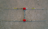 |
RA-2AHS, RA-2A Antenna with Reinforced Center "H" Section The joints on the RA-2A antenna are reinforced to add durability. Cable length required is aircraft dependent.
|
Omni-Directional Antennas and Accessories
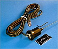 |
RA-5B Omni-Directional Antenna Base-loaded whip, three dBd gain, supplied with 17-foot coaxial cable and BNC connector. Mounts by bolting to aircraft inspection plate or other metal surface.
|
 |
Replacement whip and/or base loading assembly
The metal whip portion of this antenna (RA-5W) and/or the base loading assembly (CM00503-001 for RA-5A or RA-5B, and CM00503-002 for RA-22) can be ordered separately as replacement parts.
|
 |
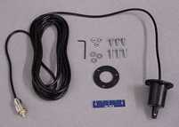
RA-5P Replacement Coaxial Cable and Base For RA-5B Antenna.
|
 |
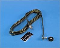
RA-10 Omni-Directional, Special Whip Antenna Requires no ground plane, 2.4 dBd. Supplied with 20-foot coaxial cable and BNC connector. The RA-10 also includes a whip portion similar to that used on the RA-5A and RA-5B antennas. Suitable for mounting on fabric-covered aircraft such as the Super Cub.
|
Antenna Control Units
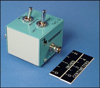 |
TAC-2 Control Box Used to switch between two antennas, with "right", "left" and "both" positions. Typically used to combine two antennas or switch between antennas mounted on right and left struts of aircraft to aid in aerial location of transmitter. Warranted for 100,000 operations.
|
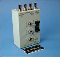 |
TAC-7 Control Box Used to switch between two antennas, with "right", "left", and "both" positions. In addition to switching between left and right antennas, there is an added capacity to switch a third (auxiliary) antenna. The third antenna is typically an omni-directional antenna, such as the RA-5B; however it could be another directional antenna, such as the RA-2A mounted on a pivot. The TAC-7 allows the option of plugging in a remote (yoke-mounted) toggle switch to select between the left and right antennas. The toggle switch (e.g. TPT-1 or TPT-2) not included. The TAC-7 is powered by a 9-volt battery (included).
|
For more information, including tech specs, on the Telonics TAC-7, see issue V 7, N3, Fall & Winter 1994 ("TAC-7 Electronic Antenna Switch Box") of the Telonics Quarterly.
Antenna Control Unit Accessories
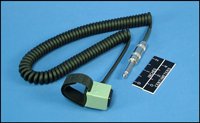 |
TPT-2 Toggle Switch With Velcro band and coil cord for yoke- or stick-mounting and use with the TAC-7.
|
Coaxial Cables
Fabricated with low-loss type RG-58A/U (0.195 inch diameter) cable. Suitable for temperatures of -40º to +80º C. Not recommended for runs longer than 25 feet.
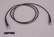 |
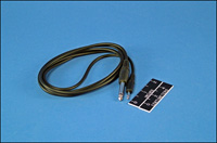
RW-2 Five-foot length, BNC male connector on each end. Used for connection of either the TAC-2 or TAC-7 to the telemetry receiver.
|
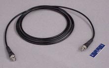 |
RW-3-9 (Nine-foot length)
RW-3-12 (12-foot length)
RW-3-17 (17-foot length) - suitable length for most aircraft
RW-3-25 (25-foot length)
When ordering, specify terminations: BNC/BNC (male/male) or BNC (male)/pigtail. Telonics receivers and the RA-2AHS antenna use the BNC/BNC terminations.
|
Headphones and Headsets
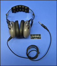 |
RH-2 Headphones High quality, noise canceling, low impedance headphones designed for heavy use. Supplied with a straight cord, 0.25" plug, and foam filled ear seals.
These headphones replace the RH-1 headphones. |
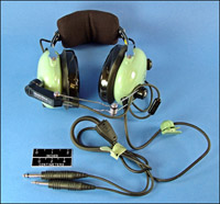 |
TAH-2 High Quality David Clark Headset Amplified dynamic, noise-canceling microphone with adjustable gain, adjustable volume control; five-foot straight cord with PJ-068 and PJ-055 standard aircraft plugs, 550 grams, 600 ohm impedance.
|
Headphone and Headset Accessories
 |
RW-4A "Y" Adapter Allows the use of two low-impedance headsets with a single receiver. One 1/4-inch audio plug, and two 1/4-inch audio jacks.
|
Aircraft Intercom and Audio Distribution Systems
A basic aircraft audio distribution system includes the SPO-22 or SPO-42 Intercom, the telemetry receiver, and TAH-2 Headsets.
 |
SPO-22 Transcom II Aircraft Intercom and Audio Distribution System Automatic activation offers pilot-to-passenger hands-free communication, push-too-talk control of VHF ATC aircraft radio, input for one telemetry receiver, and output for conventional audio tape recorder to log cockpit audio and telemetry data. ATC radios may be controlled by either pilot or copilot. Powered by an internal 9V battery, the unit provides approximately 40 hours of operation. A four-foot cord is also included for powering via a cigarette lighter jack. Standard model is designed for two headsets, with headsets purchased separately. (Headsets are required for each person who will be communicating through the system).
|
 |
SPO-42 Four-Way Aircraft Audio Same features as SPO-22, but includes an auxiliary unit for the rear sear with inputs for two additional headsets. Permits four people to have voice-actuated communications and monitor telemetry.
|
Miscellaneous Accessories
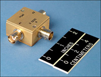 |
TAC-4 Two-Port Peak Combiner/Splitter Zero degree phase shifter (combines two 50 ohm signal sources and provides a matched 50 ohm combined output). Used to split an incoming signal from an antenna system for the simultaneous use of two receivers.
|
 |
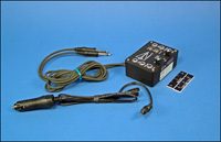
RP-3-12 12-Volt DC Charge Cord Allows powering the TR-4 or TR-5 Receiver from a 12 VDC negative ground electrical system. The plug on this cord requires a cigarette-lighter jack on the power source.
|
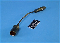 |
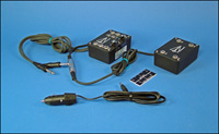
RP-3-24 24-28 Volt DC Charging Adapter Allows powering of a TR-4 or TR-5 Receiver from 24-28 VDC negative ground electrical system (e.g., an aircraft power supply) when used in conjunction with RP-3-12.
|
 |
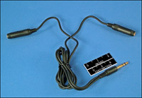
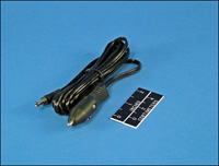
RW-8 Adapter Cable 1/4-inch phone plug to 1/8-inch phone plug, as used for connection of TR-5 Receiver to aircraft intercom system.
|
Legacy - Antenna Mounting Brackets
This information on discontinued products is provided for individuals who are still using these older systems. Product descriptions may be time sensitive or even outdated. Please contact Telonics if you have questions.
Telonics supports these products as possible based on availability of parts, software, or other considerations; but no longer sells them new.
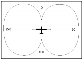
TAB-1 through TAB-6 brackets are sold as pairs. They are designed to secure RA-2A or RA-2AHS antennas to the struts of high-winged light aircraft in left-looking and right-looking orientations. The combined antenna pattern is as shown below. A TAC-2 Control Box is used to switch between the right, left, and both antennas.
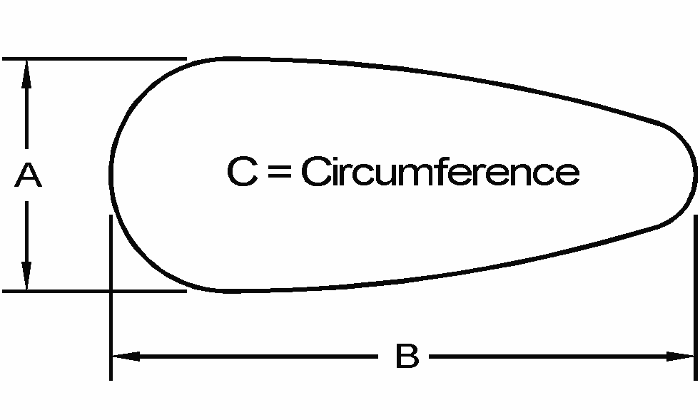
| Model | Dimensions | Common Aircraft | ||
|---|---|---|---|---|
| A | B | C | ||
| TAB-1 | 2.06 inches | 4.75 inches | 11.00 inches | Cessna 150, 172 |
| TAB-2 | 2.44 inches | 5.75 inches | 13.50 inches | Cessna 206, 207, 185 |
| TAB-3 | 1.63 inches | 3.88 inches | 8.75 inches | PA-22 (Tripacer) BC-12 (Taylor Craft) PA-18 (Super Cub) |
| TAB-4 | 1.38 inches | 2.38 inches | 6.00 inches | J3 (Piper Cub) |
| TAB-5 | 2.19 inches | 5.00 inches | 12.00 inches | Cessna 180, 182, 150-Aerobat |
| TAB-6 | 1.43 inches | 3.37 inches | 8.00 inches | Christen/Aviat-Husky |
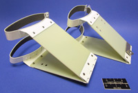
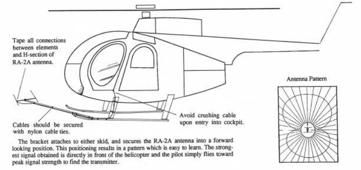
THB-1 Antenna Mounting Bracket for Hughes 500 series helicopters
Holds one RA-2A or RA-2AHS in a forward-looking orientation by attachment to one skid as shown below.
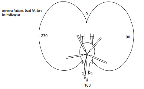
THB-3 Antenna Mounting Brackets for Hughes 500 series helicopters
This is a pair of THB-1 brackets with adapters designed to hold two RA-2A (RA-2AHS) antennas to the skids of a Hughes 500 series helicopter in left- and right-facing orientation. The antennas are combined using a TAC-2 Control Box.
Advisory Note concerning FAA regulations on mounting brackets.
Regulations governing the attachment of equipment to aircraft vary depending on ownership, use and location. Users should check with appropriate authorities regarding current regulations. The International Association of Natural Resource Pilots is a source that can make suggestions based on practical experience. You may also wish to refer to the Federal Aviation Regulations concerning type certification requirements.
FAA inspection standards vary depending on how individual FAA inspectors classify the bracket and regional FAA practices and policies.
Government owned aircraft can often mount the brackets using a simple logbook signoff. Privately held aircraft require FAA inspection to comply with FAA rules. Compliance requirements within the FAA have not been consistent from inspector to inspector or region to region.
In some parts of the US, aircraft brackets are considered a "minor alteration" and a simple logbook sign off can be completed by a certified A&P to achieve full compliance with FAA rules.
In other regions a certified mechanic fills out an FAA form 337 Major Airframe Alteration. The form describes the alteration (installation). This form is then submitted to the FSDO for a field approval. This approval is for a specific aircraft serial number and must be done again even if you outfit a second aircraft of the same model.
In other areas of the country inspectors have asked for a Supplemental Type Certificate (STC). An STC is not available from Telonics for any of our antenna mounting brackets although the user may choose to pursue an STC on their own using their A&P and at their own expense. If the STC is required by your FCC inspector, be aware the process can be expensive and time consuming. The Ohio Department of Transportation has an STC for the Cessna 182 (STC SA182CH). STCs are based on aircraft model so mounting on one Cessna aircraft does not mean that the bracket is approved for other Cessna aircraft models.